Scuffing
Overview
Scuffing can occur in high speed/high load contacts, where the breakdown of both EHL and boundary film leads to metal-metal welding between the surfaces, causing high friction, noise, vibration and wear. The standard testing methods currently used to evaluate the scuffing performance of lubricants are unable to distinguish between the lubricants with high concentration of EP and antiwear additives. These tests use either a pure sliding or a rolling sliding contact, and so at the high sliding speeds needed for scuffing to occur a significant EHL can be formed, protected the surfaces. A contra-rotation method can be used to achieve the high sliding speeds needed for scuffing, while simultaneously maintaining a low entrainment speed, limiting the formation of an EHL film. Using contra-rotation it is envisaged that an accurate testing method can be developed, that can be used to screen the scuffing performance of lubricants, including those with high concentrations of EP and antiwear additives.
Introduction
Scuffing is a phenomenon that occurs when a lubricant fails to protect two metal surfaces of a mechanical component. The lack of lubricant protection leads to direct metal-metal contact between the surfaces, and subsequently, high friction, noise, vibration and wear leading to the likely failure of the mechanical component.
The scuffing performance of lubricants can currently be evaluated using three standard testing methods, these are shown in Table 1.
- Table 1: Standard Scuffing Tests
| Testing Equipment | ASTM Method Number |
| Four Ball | D2783-88 |
| FZG | D5182-97 |
| Timken Cup on Block | D2782-94 |
Unfortunately, these methods are unable to distinguish between the best scuffing resistant lubricants. This limits the development of lubricants for the ever increasingly complex and harsh conditions found inside machines. A new scuffing method should be developed that can be used to evaluate the scuffing resistance performance of modern oils containing high concentrations of Extreme Pressure (EP) and Antiwear additives. This requires the development of a test that subjects the lubricant to more strenuous conditions in terms on sliding speed and contact pressure.
In 1948, Blok (1) published a paper suggesting that contra-rotation could be used as an efficient way of evaluating the scuffing performance of lubricants. By rotating the samples in opposite and equal speeds, a theoretical EHL film thickness of zero will be produced, while simultaneously subjecting the surface to the high sliding speeds needed for scuffing. Therefore the protection of the surface by the lubricant comes solely from the action of the boundary lubricating additives such as friction modifiers, antiwear and extreme pressure additives.
Proposed Research Method
PCS Instruments currently manufacture two pieces of equipment that can be used for this investigation, the Mini Traction Machine (MTM) and the Micro-pitting rig (MPR). Both machines are capable of producing the contra-rotation contact desired in this research. The previous work on scuffing evaluation using contra-rotation has been carried out on the MTM (2,3), which has yielded some interesting results. A small number of tests have also been carried out on the MPR, using contra-rotation. This has shown some correlation using a step load test.
The following upper samples manufactured from AISI 52100 are available for the MTM2:
- Table 2: Upper Specimens available for the MTM2
| Description | Roughness (Ra) | Part Code |
| ¾ “ Ball | < 25 nm | BALLD |
| ½ “ Ball | < 25 nm | BALLD1/2 |
| Barrel with 1 mm radius (Rough) | 120 nm | MTMBARREL1MMR |
| Barrel with 1 mm radius (Smooth) | 15 nm | MTMBARREL1MMS |
| Barrel with 0.8 mm radius (Rough) | 120 nm | MTMBARREL08MMR |
| Barrel with 0.8 mm radius (Smooth) | 15 nm | MTMBARREL08MMS |
The lower specimen is a disk. The standard MTM2 disk, has a Vickers hardness of 760. The smooth disk has a roughness of below 0.005 µm Ra and the rough disc has a roughness of 0.150 µm.
A wide range of contact pressures can be achieved by using the standard AISI 52100 disk and the available upper specimens, which can be a ball or a barrel. A load of between 5 and 75 N can be applied between these specimens on the MTM2, yielding contact pressures of between 0.5 and 3.4 GPa. The contact pressure possible for each of the available upper specimens is shown in Figure 1: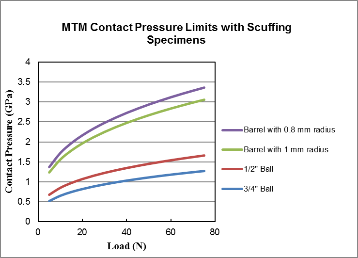
All previous test have been carried out using the AISI 52100 samples, this is a bearing steel. Whereas gears and other gear tests use steels such as DIN: 20MnCr5. It is possible to manufacture the samples desired from this or a similar material for testing, to ensure no large difference in performance is found.
The following oils are available from PCS Instruments. These include reference oils (Table 3) and commercial oils from Mobil (Table 4).
- Table 3: Reference oils
| Lubricant Name | FZG fail stage (D 5182) |
| RL219 | 5>6 |
| RL214 | 9>11 |
| RL237 |
- Table 4: Commercial Gear Oils
| Lubricant Name | FZG fail stage (D5182) |
| Mobil DTE oil light | 8 |
| Mobil DTE 68 | 10 |
| Mobil SHC 626 | 11 |
| Mobil DTE 10 Excel 68 | 12 |
| Mobil SHC 630 | 13 |
| Mobil SHC XMP 220 | 14+ |
Possible Interests
The mechanism of scuffing, including the critical parameters for its occurrence, is still poorly understood. By understanding these better, a more accurate test for scuffing evaluation can be designed.
It is anticipated that more information can be gleaned from the friction results generated at the point of scuffing. Figure 2 below shows an example of the friction trace that is produced during a step load scuffing test. 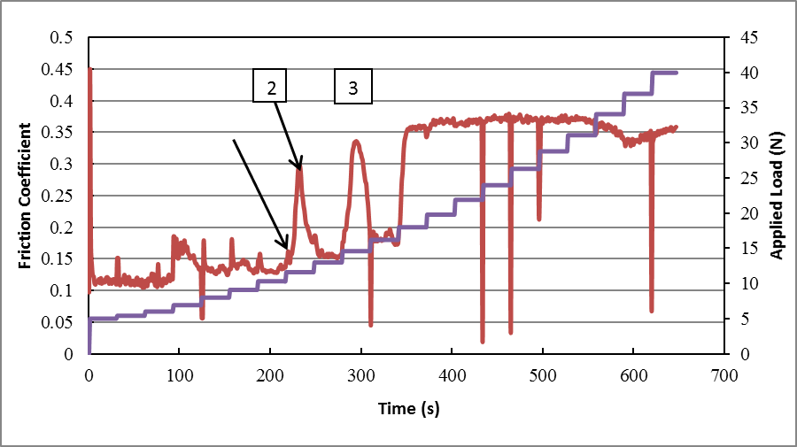
The sharp rise in friction, labelled as (1) on Figure 2, is currently believed to indicate the occurrence of scuffing on discrete parts on the metal surfaces. Small welding marks are found on the surfaces after this event. The friction can then recover (Figure 2, (2)), showing a sharp decline back to a boundary friction coefficient. This recovery is believed to be due to a drop in pressure in the contact or reaction of additives on the freshly exposed sample surface. The drop in pressure may occur due to wear of the non-conformal sample (ball or barrel), leading to subsequent lower flash temperatures in the contact to below the critical scuffing temperature. The reaction of the additives on the freshly exposed metal surfaces during rubbing will have two effects: to provide an antiwear barrier reducing further wear, and lowering the friction. At a certain load step the friction coefficient can then increase sharply and remain high through the remainder of the test (Figure 2, (3))
For a better understanding of the mechanism of scuffing, the flash temperatures in the contact could be calculated.
To ensure that the nominal contact pressure matches actual contact pressure, the test could be stopped periodically to allow the measurement of the radius on the barrel, or measure the radius of the wear track on the ball.
Expected Outcome
A scuffing “map” may be investigated and constructed, through the careful execution of many tests. This will include the point of scuffing of a selection of oils over a range of contact pressures and sliding speeds. The ideal situation would be that future users of the scuffing test can then use this map to accurately compare the performance of new formulations.
A scuffing map consisting of a selection of results produced at Imperial College London and PCS Instruments is plotted below in Figure 3. The axes show the limitations of the MTM2 in terms of the sliding speeds and contact pressures achievable with the samples shown in Table 2. The points plotted on the map show the contact pressure and sliding speed at which scuffing has been deemed to occur.
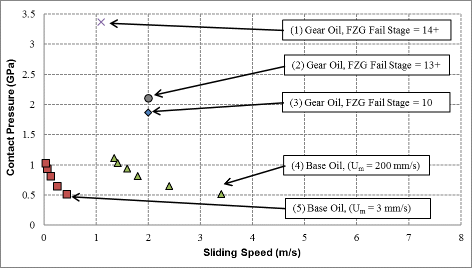
The base oils (4 & 5) were tested using a ¾” ball on a smooth disk, in two different lubrication regimes. As expected the test operating with a higher entrainment speed (mixed regime) required higher sliding speeds to exhibit scuffing, than the test carried out in the boundary regime.
The gear oils (1, 2 & 3) were tested using a barrel with a 0.8 mm radius, allowing higher pressure to be achieved. Test 1 had a constant load (75 N) and entrainment speed (0.01 m/s) with a linearly increasing sliding speed. Tests 2 & 3 had a constant sliding speed (2 m/s) and entrainment speed (0.01 m/s) with the load increasing step wise. The ability to show scuffing of these gear oils in a short bench top test is significant, as the tests currently used to study the scuffing performance of these oils are very long and expensive.
A map like this one could be developed further by carrying out tests with different conditions to produce patterns like that shown for the base oils (4 & 5). By doing this for the gear oils, it is expected that certain zones will be highlighted that could be used to distinguish between the scuffing performance of gear oils. The appropriate conditions can then be selected when screening new oils on the MTM2 using the map as a reference.
Figure 3 also shows the potential conditions still available that can be used when screening the scuffing performance of gear oils. Sliding speeds of up to 8 m/s are achievable (with zero entrainment speed), along with contact pressures up to 3.4 GPa.
References
(1) Blok, H. “Gear Wear as Related to Viscosity of Gear Oils” Proc. Summer Conference – MIT, Mechanical Wear, 1948, ASME, Vol. 61, 25, pp. 39-46
(2) Salt, C. “Development and Application of a New Scuffing Test.” 4M project report, Imperial College London, 2006
(3) Maguire, J. “Development of a New Scuffing Test” 4M project report, Imperial College London, 2007